

How To Draw A Line Between 2 Vertices Pthon
Editing
- Setting the Snapping Tolerance and Search Radius
- Snapping tolerance
- Search radius
- Topological editing
- Enable topological editing
- Avert intersections of new polygons
- Enable snapping on intersections
- Geometry Checker
- Digitizing an existing layer
- Adding Features
- Node Tool
- Basic operations
- The Vertex Editor
- Cutting, Copying and Pasting Features
- Deleting Selected Features
- Saving Edited Layers
- Saving multiple layers at once
- Advanced digitizing
- Undo and Redo
- Rotate Feature(s)
- Simplify Characteristic
- Add Part
- Delete Role
- Add Ring
- Fill up Ring
- Delete Band
- Reshape Features
- Offset Curves
- Dissever Features
- Split parts
- Merge selected features
- Merge attributes of selected features
- Rotate Betoken Symbols
- Outset Point Symbols
- Automatic Tracing
- The Advanced Digitizing panel
- Concepts
- Snapping Settings
- Keyboard shortcuts
- Absolute reference digitizing
- Relative reference digitizing
- Continuous lock
- Parallel and perpendiculars line
- Construction mode
QGIS supports various capabilities for editing OGR, SpatiaLite, PostGIS, MSSQL Spatial and Oracle Spatial vector layers and tables.
Tip
Concurrent Edits
This version of QGIS does not track if somebody else is editing the aforementioned characteristic at the same fourth dimension as you are. The last person to save its edits wins.
Setting the Snapping Tolerance and Search Radius
For an optimal and accurate edit of the vector layer geometries, we need to set an advisable value of snapping tolerance and search radius for features vertices.
Snapping tolerance
Snapping tolerance is the distance QGIS uses to search for the closest vertex and/or segment you are trying to connect to when y'all set a new vertex or move an existing vertex. If you aren't inside the snapping tolerance, QGIS will leave the vertex where you release the mouse push, instead of snapping it to an existing vertex and/or segment. The snapping tolerance setting affects all tools that work with tolerance.
- A general, project-wide snapping tolerance tin can exist defined by choosing
 , Digitizing tab. You lot can select between 'To vertex', 'To segment' or 'To vertex and segment' equally default snap mode. You lot tin also ascertain a default snapping tolerance and a search radius for vertex edits. The tolerance can be set either in map units or in pixels. The advantage of choosing pixels is that the snapping tolerance doesn't have to be changed afterwards zoom operations. In our pocket-sized digitizing projection (working with the Alaska dataset), we ascertain the snapping units in feet. Your results may vary, but something on the order of 300 ft at a calibration of 1:10000 should exist a reasonable setting.
 - A layer-based snapping tolerance that overrides the global snapping options can be defined by choosing . It enables and adjusts snapping mode and tolerance on a layer basis (run across figure_edit_snapping ). This dialog offers 3 different modes to select the layer(s) to snap to:
- Current layer: simply the active layer is used, a convenient way to ensure topology within the layer being edited
- All layers: a quick and elementary setting for all visible layers in the project then that the pointer snaps to all vertices and/or segments. In most cases it is sufficient to employ this snapping way.
- Advanced: if you need to edit a layer and snap its vertices to another layer, ensure the target layer is checked and increment the snapping tolerance to a greater value. Furthermore, snapping will never occur to a layer that is not checked in the snapping options dialog, regardless of the global snapping tolerance. So be certain to mark the checkbox for those layers that you demand to snap to.
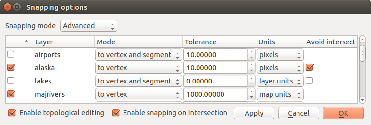
Edit snapping options on a layer footing (Avant-garde style)
Tip
Command the list of layers to snap
The Snapping Options dialog is by default populated with parameters (mode, tolerance, units) set in the global Digitizing tab. To avoid layers beingness checked by default in the Avant-garde mode and hence prepare snappable, ascertain the Default Snap fashion to Off .
Snapping tolerance can be set in pixels or map units (the units of the map view). While in the Advanced layer selection mode, information technology is possible to use a snapping tolerance that refers to layer units , the units of the reprojected layer when 'on-the-fly' CRS transformation is on.
Search radius
Search radius is the distance QGIS uses to search for the closest vertex you lot are trying to select when yous click on the map. If you lot aren't within the search radius, QGIS won't find and select whatsoever vertex for editing. The search radius for vertex edits can be divers under tab. This is the same place where you define the general, project-broad snapping tolerance.
Snap tolerance and search radius are ready in map units or pixels , and then you may discover you need to experiment to become them gear up correct. If you lot specify likewise big of a tolerance, QGIS may snap to the wrong vertex, specially if yous are dealing with a large number of vertices in close proximity. Set search radius too modest, and information technology won't find anything to movement.
Topological editing
Besides layer-based snapping options, y'all tin can besides define topological functionalities in the Snapping options... dialog in the (or ) menu. Here, you can define  Enable topological editing, and/or for polygon layers, actuate the Avert Intersections choice.
Enable topological editing
The selection Enable topological editing is for editing and maintaining mutual boundaries in features mosaics. QGIS 'detects' shared boundary by the features, so you only have to motility a common vertex/segment in one case, and QGIS will take care of updating the neighboring features.
Avert intersections of new polygons
A second topological option called Avoid intersections prevents y'all to draw new features that overlap an existing one. Information technology is for quicker digitizing of adjacent polygons. If you already accept one polygon, it is possible with this option to digitize the 2d i such that both intersect, and QGIS then cuts the second polygon to the boundary of the existing one. The advantage is that you don't take to digitize all vertices of the common boundary.
Note
If the new geometry is totally covered by existing ones, it gets cleared and the new feature will have no geometry when immune by the provider, otherwise saving modifications will brand QGIS pop-upwardly an error bulletin.
Warning
Use cautiously the Avert Intersections option
Because the option cuts or clears geometry of any overlaping feature from any polygon layer, practice non forget to uncheck this option one time you no longer need it otherwise, you can get unexpected geometries.
Enable snapping on intersections
Another pick is to use Enable snapping on intersection. Information technology allows you to snap on an intersection of background layers, even if there'southward no vertex on the intersection.
Geometry Checker
A core plugin can assistance the user to find the geometry invalidity. You tin observe more data on this plugin at Geometry Checker Plugin.
Digitizing an existing layer
By default, QGIS loads layers read-only. This is a safeguard to avoid accidentally editing a layer if there is a slip of the mouse. Notwithstanding, you can choose to edit any layer every bit long as the data provider supports it (run across Exploring Data Formats and Fields), and the underlying information source is writable (i.e., its files are non read-only).
Tip
Restrict edit permission on layers within a project
From the tab, You tin can choose to set any layer read-only regardless the provider permission. This tin exist a handy way, in a multi-users surroundings to avoid unauthorized users to mistakenly edit layers (east.g., shapefile), hence potentially corrupt data. Note that this setting only applies within the current project.
In full general, tools for editing vector layers are divided into a digitizing and an advanced digitizing toolbar, described in section Avant-garde digitizing. You can select and unselect both under . Using the basic digitizing tools, you can perform the post-obit functions:
| Icon | Purpose | Icon | Purpose |
|---|---|---|---|
 | Current edits |  | Toggle editing |
 | Add Feature: Capture Point |  | Add together Feature: Capture Line |
 | Add together Feature: Capture Polygon |  | Move Feature |
 | Add Circular Cord |  | Add together Round String Past Radius |
 | Node Tool |  | Delete Selected |
 | Cut Features |  | Re-create Features |
 | Paste Features |  | Save layer edits |
Tabular array Editing: Vector layer bones editing toolbar
Annotation that while using any of the digitizing tools, you tin still zoom or pan in the map sail without losing the focus on the tool.
All editing sessions showtime past choosing the Toggle editing choice plant in the context carte of a given layer, from the attribute table dialog, the digitizing toolbar or the menu.
In one case the layer is in edit fashion, additional tool buttons on the editing toolbar will become available and markers will appear at the vertices of all features unless Show markers simply for selected features option under menu is checked.
Tip
Relieve Regularly
Recall to Save Layer Edits regularly. This volition besides cheque that your data source can accept all the changes.
Adding Features
Yous can use the Add Feature, Add Feature or Add Feature icons on the toolbar to add new feature (point, line and polygon) into the current layer.
The adjacent buttons Add circular string or Add circular string past radius allow users to add line or polygon features with a round geometry.
To create features with these tools, you showtime digitize the geometry then enter its attributes. To digitize the geometry, left-click on the map area to create the first point of your new feature.
For linear or curved geometries, go along on left-clicking for each additional indicate yous wish to capture or use automatic tracing capability to accelerate the digitization. Yous tin switch back and forth between linear Add feature tool and curved Add round string... tools to create compound curved geometry. Pressing Delete or Backspace key reverts the last node yous add. When y'all have finished adding points, right-click anywhere on the map area to confirm yous accept finished inbound the geometry of that feature.
Note
Curved geometries are stored equally such only in compatible data provider
Although QGIS allows to digitize curved geometries within whatsoever editable data format, you need to exist using a data provider (e.g. PostGIS, GML or WFS) that supports curves to have features stored as curved, otherwise QGIS segmentizes the circular arcs. The memory layer provider likewise supports curves.
Tip
Customize the digitizing safety band
While capturing polygon, the by-default scarlet prophylactic band can hide underlying features or places you'd like to capture a point. This tin can be fixed by setting a lower opacity (or blastoff channel) to the safety band's Fill Colour in bill of fare. You tin besides avoid the use of the safety band past checking Don't update rubber band during node editing.
The attribute window will appear, allowing you to enter the information for the new characteristic. Figure_edit_values shows setting attributes for a fictitious new river in Alaska. All the same, in the Digitizing bill of fare nether the menu, you lot tin can also activate:
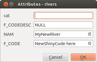
Enter Attribute Values Dialog after digitizing a new vector feature
With the Move Feature(s) icon on the toolbar, you tin move existing features.
Cutting, Copying and Pasting Features
Selected features can be cut, copied and pasted between layers in the aforementioned QGIS projection, as long as destination layers are set to Toggle editing beforehand.
Tip
Transform polygon into line and vice-versa using copy/paste
Copy a line characteristic and paste it in a polygon layer: QGIS pastes in the target layer a polygon whose boundary corresponds to the closed geometry of the line feature. This is a quick fashion to generate different geometries of the same data.
Features can also be pasted to external applications every bit text. That is, the features are represented in CSV format, with the geometry data appearing in the OGC Well-Known Text (WKT) format. WKT and GeoJSON features from outside QGIS can also be pasted to a layer within QGIS.
When would the copy and paste function come in handy? Well, it turns out that you can edit more than one layer at a time and copy/paste features between layers. Why would nosotros desire to exercise this? Say we demand to do some piece of work on a new layer but only need 1 or two lakes, not the 5,000 on our big_lakes layer. We can create a new layer and utilize copy/paste to plop the needed lakes into it.
As an case, we volition re-create some lakes to a new layer:
- Load the layer you desire to copy from (source layer)
- Load or create the layer you desire to copy to (target layer)
- First editing for target layer
- Brand the source layer agile by clicking on it in the fable
- Utilize the
 Select Features by area or single click tool to select the feature(s) on the source layer
 - Click on the Copy Features tool
- Brand the destination layer active past clicking on it in the fable
- Click on the Paste Features tool
- Stop editing and save the changes
What happens if the source and target layers accept dissimilar schemas (field names and types are not the same)? QGIS populates what matches and ignores the rest. If you don't intendance nearly the attributes beingness copied to the target layer, it doesn't matter how you pattern the fields and data types. If you want to brand certain everything - the feature and its attributes - gets copied, make sure the schemas match.
Note
Congruency of Pasted Features
If your source and destination layers apply the aforementioned projection, then the pasted features will have geometry identical to the source layer. Nevertheless, if the destination layer is a different projection, and so QGIS cannot guarantee the geometry is identical. This is merely because at that place are small rounding-off errors involved when converting between projections.
Tip
Copy string attribute into another
If you have created a new cavalcade in your attribute table with type 'cord' and desire to paste values from some other aspect cavalcade that has a greater length the length of the column size will be extended to the aforementioned corporeality. This is because the GDAL Shapefile driver starting with GDAL/OGR 1.10 knows to motorcar-extend string and integer fields to dynamically accommodate for the length of the data to exist inserted.
Deleting Selected Features
If we want to delete an entire feature (attribute and geometry), we can do that by offset selecting the geometry using the regular Select Features past area or unmarried click tool. Selection can also be done from the attribute table. Once you accept the pick set, press Delete or Backspace central or use the Delete Selected tool to delete the features. Multiple selected features can be deleted at once.
The Cut Features tool on the digitizing toolbar tin can also exist used to delete features. This effectively deletes the feature merely also places it on a "spatial clipboard". Then, we cut the feature to delete. We could and then utilize the Paste Features tool to put information technology back, giving us a one-level undo adequacy. Cut, copy, and paste work on the currently selected features, pregnant we can operate on more than i at a time.
Saving Edited Layers
When a layer is in editing mode, any changes remain in the retentiveness of QGIS. Therefore, they are not committed/saved immediately to the information source or disk. If yous want to save edits to the current layer just want to keep editing without leaving the editing mode, y'all tin can click the Save Layer Edits push button. When you turn editing mode off with Toggle editing (or quit QGIS for that matter), you are also asked if y'all desire to relieve your changes or discard them.
If the changes cannot be saved (e.g., disk total, or the attributes have values that are out of range), the QGIS in-memory state is preserved. This allows yous to adjust your edits and try again.
Tip
Data Integrity
It is ever a proficient thought to back up your data source before you starting time editing. While the authors of QGIS have made every effort to preserve the integrity of your data, we offer no warranty in this regard.
Saving multiple layers at once
This characteristic allows the digitization of multiple layers. Choose  Save for Selected Layers to save all changes yous fabricated in multiple layers. Yous also have the opportunity to
  Rollback for Selected Layers, so that the digitization may exist withdrawn for all selected layers. If you want to stop editing the selected layers,
  Cancel for Selected Layer(s) is an easy mode.
The same functions are available for editing all layers of the projection.
Tip
Use transaction group to edit, salvage or rollback multiple layers changes at once
When working with layers from the aforementioned PostGreSQL database, activate the Automatically create transaction groups where possible option in to sync their beliefs (enter or exit the edit mode, relieve or rollback changes at the same time).
Advanced digitizing
| Icon | Purpose | Icon | Purpose |
|---|---|---|---|
 | Enable Avant-garde Digitizing Tools |  | Enable Tracing |
 | Undo |  | Redo |
 | Rotate Feature(due south) |  | Simplify Characteristic |
 | Add Ring |  | Add Part |
 | Fill Ring | ||
 | Delete Ring |  | Delete Part |
 | Starting time Curve |  | Reshape Features |
 | Dissever Parts |  | Divide Features |
 | Merge Attributes of Selected Features |  | Merge Selected Features |
 | Rotate Point Symbols |  | First Signal Symbols |
Table Advanced Editing: Vector layer advanced editing toolbar
Disengage and Redo
The Undo and Redo tools allows you to disengage or redo vector editing operations. There is likewise a dockable widget, which shows all operations in the undo/redo history (come across Figure_edit_undo). This widget is not displayed past default; it tin be displayed past correct-clicking on the toolbar and activating the Undo/Redo Panel checkbox. The Disengage/Redo adequacy is however agile, even if the widget is non displayed.
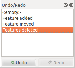
Redo and Undo digitizing steps
When Undo is hit or Ctrl+Z (or Cmd+Z ) pressed, the country of all features and attributes are reverted to the state before the reverted operation happened. Changes other than normal vector editing operations (for case, changes done past a plugin) may or may not exist reverted, depending on how the changes were performed.
To use the undo/redo history widget, simply click to select an operation in the history list. All features will be reverted to the country they were in after the selected operation.
Rotate Characteristic(south)
Use Rotate Feature(due south) to rotate one or multiple features in the map canvas. Press the Rotate Feature(southward) icon and and so click on the feature to rotate. Either click on the map to place the rotated feature or enter an angle in the user input widget. If you want to rotate several features, they shall be selected start.
If you enable the map tool with feature(s) selected, its (their) centroid appears and volition exist the rotation anchor bespeak. If you want to move the anchor point, hold the Ctrl button and click on the map to identify it.
If you agree Shift before clicking on the map, the rotation will be done in 45 degree steps, which can exist modified afterward in the user input widget.
To abort feature rotation, you need to click on Rotate Feature(south) icon.
Simplify Feature
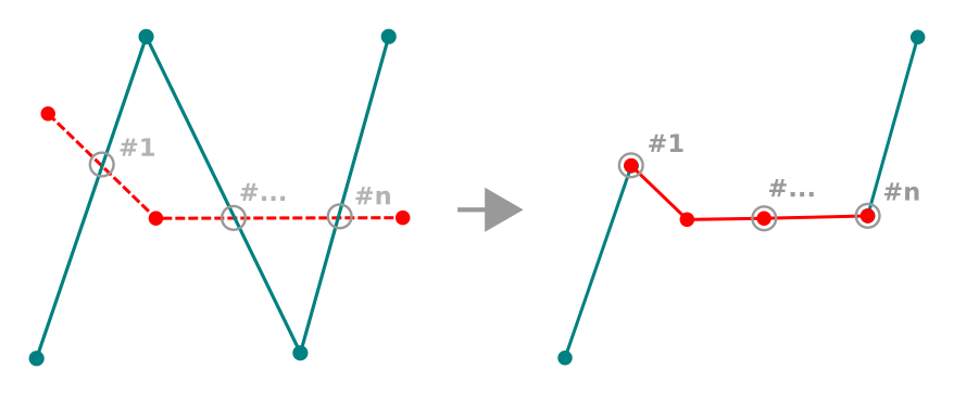
The Simplify Feature tool allows you to reduce the number of vertices of a feature, as long as the geometry remains valid. With the tool y'all can also simplify many features at in one case or multi-role features.
First, click on the feature or elevate a rectangle over the features. A dialog where you lot can ascertain a tolerance in map units , layer units or pixels pops upwards and a colored and simplified copy of the feature(due south), using the given tolerance, appears over them. QGIS calculates the amount of vertices that can be deleted while maintaining the geometry. The higher the tolerance is the more vertices tin can be deleted. When the expected geometry fits your needs only click the [OK] button. The tolerance you used will be saved when leaving a project or when leaving an edit session. And so you tin can go back to the same tolerance the next time when simplifying a characteristic.
To abort feature simplification, you need to click on Simplify Feature icon.
Notation
Unlike the characteristic simplification option in card which simplifies the geometry just for rendering, the Simplify Feature tool permanently modifies characteristic's geometry in data source.
Add Part
You can Add Part to a selected feature generating a multipoint, multiline or multipolygon feature. The new part must exist digitized exterior the existing one which should be selected beforehand.
The Add Office can also be used to add a geometry to a geometryless characteristic. Kickoff, select the feature in the attribute tabular array and digitize the new geometry with the Add Part tool.
Delete Function
The Delete Part tool allows you to delete parts from multifeatures (e.g., to delete polygons from a multi-polygon feature). This tool works with all multi-function geometries: point, line and polygon. Furthermore, it tin be used to totally remove the geometric component of a characteristic. To delete a part, merely click within the target part.
Add Ring
You tin can create ring polygons using the Add together Band icon in the toolbar. This ways that inside an existing area, it is possible to digitize farther polygons that volition occur as a 'hole', so only the expanse between the boundaries of the outer and inner polygons remains as a ring polygon.
Fill Ring
You tin can use the Fill Ring role to add a ring to a polygon and add together a new characteristic to the layer at the same time. Using this tool, you lot simply take to digitize a polygon within an existing one. Thus you lot need not first use the Add Ring icon and so the Add feature function anymore.
Delete Ring
The Delete Ring tool allows you to delete rings within an existing polygon, by clicking inside the hole. This tool only works with polygon and multi-polygon features. Information technology doesn't change annihilation when it is used on the outer ring of the polygon.
Reshape Features
You tin reshape line and polygon features using the Reshape Features tool on the toolbar. For lines, information technology replaces the line part from the first to the last intersection with the original line.
Reshape line
Tip
Extend linestring geometries with reshape tool
Employ the Reshape Features tool to extend existing linestring geometries: snap to the first or last vertex of the line and draw a new i. Validate and the feature'south geometry becomes the combination of the two lines.
For polygons, it volition reshape the polygon's boundary. For it to work, the reshape tool's line must cantankerous the polygon's purlieus at least twice. To draw the line, click on the map sheet to add together vertexes. To finish information technology, but right-click. Like with the lines, merely the segment between the commencement and the last intersections is considered. The reshape line's segments that are within the polygon will result in cropping information technology, where the ones outside the polygon will extend it.
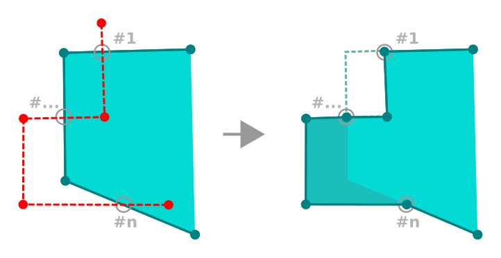
Reshape polygon
With polygons, reshaping can sometimes lead to unintended results. Information technology is mainly useful to supplant smaller parts of a polygon, not for major overhauls, and the reshape line is not allowed to cantankerous several polygon rings, as this would generate an invalid polygon.
Annotation
The reshape tool may modify the starting position of a polygon ring or a closed line. Then, the signal that is represented 'twice' will not be the same whatever more. This may non be a problem for most applications, but it is something to consider.
Offset Curves
The Offset Curve tool creates parallel shifts of line layers. The tool can be applied to the edited layer (the geometries are modified) or too to background layers (in which case it creates copies of the lines / rings and adds them to the edited layer). It is thus ideally suited for the cosmos of distance line layers. The User Input dialog pops-upward, showing the displacement altitude.
To create a shift of a line layer, you must kickoff become into editing way and actuate the Beginning Bend tool. And so click on a feature to shift information technology. Move the mouse and click where wanted or enter the desired distance in the user input widget. Your changes may so exist saved with the Save Layer Edits tool.
QGIS options dialog (Digitizing tab then Bend showtime tools section) allows you to configure some parameters like Join way, Quadrant segments, Miter limit.
Split Features
You can divide features using the Divide Features icon on the toolbar. Merely draw a line across the characteristic y'all want to carve up.
Split parts
In QGIS it is possible to divide the parts of a multi part feature so that the number of parts is increased. Just draw a line across the role you want to split using the Divide Parts icon.
Tip
Dissever a polyline feature in one-click
A single click on a snapped vertex of a line feature with the Split Features or Split Parts tool is enough to accept it carve up into new features or parts.
Merge selected features
The Merge Selected Features tool allows you lot to create a new feature by merging existing ones: their geometries are merged to generate a new one. If features don't have common boundaries, a multipolygon/multipolyline/multipoint feature is created.
First, select several features. And so printing the Merge Selected Features button. In the new dialog, you can select at the acme of the dialog which value to utilize to each field of the new feature. That value can be:
- picked from the attributes of the initial features,
- an aggregation of the initial features attributes (Minimum, Maximum, Median, Sum, Count Concatenation... depending on the blazon of the field. come across Statistical Summary Console for the full list of functions),
- skipped, significant that the field will be empty,
- or manually entered, at the bottom of the rows.
Merge attributes of selected features
The Merge Attributes of Selected Features tool allows you to apply same attributes to features without merging their boundaries. The dialog is the same as the Merge Selected Features tool's except that unlike that tool, selected objects are kept with their geometry while some of their attributes are fabricated identical.
Rotate Indicate Symbols
The Rotate Signal Symbols allows you to change the rotation of point symbols in the map canvas. Commencement of all, yous must use to the symbol a information-divers rotation: in the dialog, click the  Information-defined override widget near the Rotation choice of the highest level (preferably) of the symbol layers and choose a field in the Field Type combobox. Values of this field are hence used to rotate each feature'south symbol appropriately.
Note
Equally a global selection, setting the rotation field at the first level of the symbol applies information technology to all the underlying levels while setting it at a lower level will rotate merely this symbol layer (unless yous have a single symbol layer).
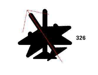
Rotate Indicate Symbols
To change the rotation of a symbol, click on a point characteristic in the map canvass with the Rotate Point Symbols and move the mouse around, holding the left button pressed. A red arrow with the rotation value will be visualized (see Figure_rotate_point). When you release the left mouse button again, the symbol is divers with this new rotation and the rotation field is updated in the layer's aspect table.
Tip
If you hold the Ctrl key pressed, the rotation will be done in fifteen caste steps.
Start Point Symbols
The Offset Point Symbols allows you to interactively change the rendered position of point symbols in the map sheet. This tool behaves like the Rotate Point Symbols tool except that it requires y'all to connect a field to the information-defined First (X,Y) property of the symbol, field which volition then be populated with the offset coordinates while moving the symbol in the map sail.
Note
The Commencement Signal Symbols tool doesn't move the point characteristic itself; you should apply the Node Tool or Motility Feature tool for this purpose.
Alert
Ensure to assign the aforementioned field to all symbol layers
If at least ii layers of the symbol have dissimilar fields assigned to their data-defined property (e.one thousand. rotation), the corresponding tool will consider that no field is assigned to the symbol holding and won't perform the action.
Automatic Tracing
Normally, when using capturing map tools (add together feature, add together part, add band, reshape and dissever), you need to click each vertex of the characteristic.
Using the automatic tracing fashion you tin can speed upward the digitization procedure. Enable the Tracing tool past pushing the icon or pressing t key and snap to a vertex or segment of a characteristic yous want to trace along. Move the mouse over another vertex or segment y'all'd similar to snap and instead of an usual straight line, the digitizing rubber band represents a path from the last betoken you snapped to the electric current position. QGIS actually uses the underlying features topology to build the shortest path between the two points. Click and QGIS places the intermediate vertices following the path. You no longer need to manually place all the vertices during digitization.
Tracing requires snapping to be activated in traceable layers to build the path. Y'all should also snap to an existing vertex or segment while digitizing and ensure that the ii nodes are topologically connectable post-obit existing features, otherwise QGIS is unable to connect them and thus traces a single direct line.
Note
Adjust map scale or snapping settings for an optimal tracing
If in that location are too many features in map display, tracing is disabled to avoid potentially long tracing construction preparation and large memory overhead. After zooming in or disabling some layers the tracing is enabled again.
Tip
Speedily enable or disable automatic tracing by pressing t cardinal
By pressing t primal, tracing can be enabled/disabled anytime even while digitizing 1 feature, so it is possible to digitize some parts of the feature with tracing enabled and other parts with tracing disabled. Tools behave every bit usual when tracing is disabled.
The Advanced Digitizing panel
When capturing, reshaping, splitting new or existing geometries y'all also have the possibility to utilise the Advanced Digitizing panel. You lot tin digitize lines exactly parallel or perpendicular to a detail angle or lock lines to specific angles. Furthermore, you can enter coordinates directly and so that you can make a precise definition of your new geometry.
The Advanced Digitizing console
Note
The tools are not enabled if the map view is in geographic coordinates.
The Advanced Digitizing panel tin can be open either with a right-click on the toolbar and choose Avant-garde Digitizing panel or in . Once the panel is visible, click the enable advanced digitizing tool push to activate the Advanced Digitizing tool.
Concepts
The aim of the Advanced Digitizing tool is to lock coordinates, lengths, and angles when moving the mouse during the digitalizing in the map sheet.
You tin also create constraints with relative or absolute reference. Relative reference means that the next vertex constraints' values will be relative to the previous vertex or segment.
Snapping Settings
Click the  button to gear up the Advanced Digitizing Tool snapping settings. You can make the tool snap to common angles. The options are:
- Do non snap to mutual angles
- Snap to 30º angles
- Snap to 45º angles
- Snap to 90º angles
You can also control the snapping to features. The options are:
- Do not snap to vertices or segments
- Snap according to project configuration
- Snap to all layers
Keyboard shortcuts
To speed up the use of Advanced Digitizing Panel, there are a couple of keyboard shorcuts available:
| Primal | Simple | Ctrl + or Alt + | Shift + |
|---|---|---|---|
| d | Set distance | Lock distance | |
| a | Prepare bending | Lock angle | Toggle relative bending to terminal segment |
| x | Prepare x coordinate | Lock 10 coordinate | Toggle relative x to last vertex |
| y | Set y coordinate | Lock y coordinate | Toggle relative y to final vertex |
| c | Toggle construction fashion | ||
| p | Toggle perpendicular and parallel modes | ||
Absolute reference digitizing
When cartoon a new geometry from scratch, it is very useful to accept the possibility to showtime digitizing vertexes at given coordinates.
For example, to add a new feature to a polygonal layer, click the button. You tin choose the X and Y coordinates where you want to start editing the feature, so:
Two blue dotted lines and a green cross identify the verbal coordinates you entered. Start digitizing past clicking on the map canvas; the mouse position is locked at the green cantankerous.
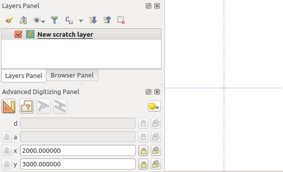
Commencement cartoon at given coordinates
You can continue digitizing by costless hand, adding a new pair of coordinates, or you can blazon the segment'southward length (distance) and bending.
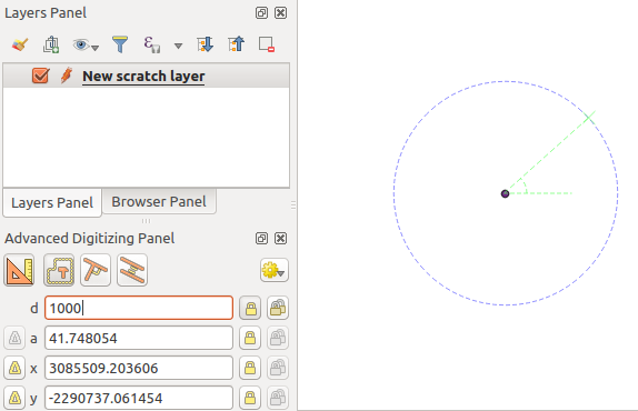
If you want to draw a segment of a given length, click the d (distance) text box (keyboard shortcut d ), type the altitude value (in map units) and press Enter or click the  button on the correct to lock the mouse in the map sheet to the length of the segment. In the map canvas, the clicked point is surrounded past a circle whose radius is the value entered in the distance text box.
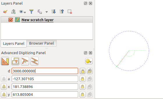
Fixed length segment
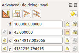
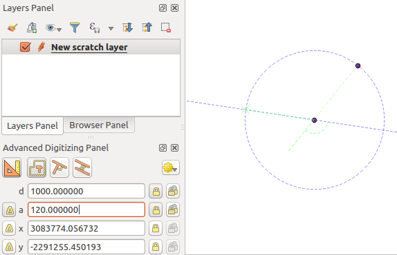
Finally, you can besides cull the angle of the segment. Every bit described before , click the a (angle) text box (keyboard shortcut a ), type the bending value (in degrees), and press Enter or click the buttons on the correct to lock it. In this way the segment will follow the desired angle:
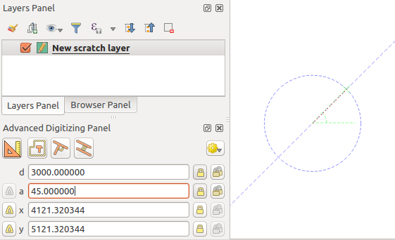
Fixed bending segment
Relative reference digitizing
Instead of using absolute values of angles or coordinates, you tin can besides utilize values relative to the last digitized vertex or segment.
For angles, y'all tin click the  push button on the left of the a text box (or press Shift + a ) to toggle relative angles to the previous segment. With that option on, angles are measured betwixt the last segment and the mouse pointer.
For coordinates, click the buttons to the left of the x or y text boxes (or press Shift + x or Shift + y ) to toggle relative coordinates to the previous vertex. With these options on, coordinates measurement will consider the last vertex to exist the x and y axes origin.
Continuous lock
Both in absolute or relative reference digitizing, angle, distance, 10 and y constraints can be locked continuously by clicking the  Continuous lock buttons. Using continuous lock allows you to digitize several points or vertexes using the same constraints.
Parallel and perpendiculars line
All the tools described above can be combined with the  Perpendicular and
  Parallel tools. These two tools allow cartoon segments perfectly perpendicular or parallel to another segment.
To describe a perpendicular segment, during the editing click the Perpendicular icon (keyboard shortcut p ) to actuate it. Earlier drawing the perpendicular line, click on the segment of an existing feature that you lot desire to be perpendicular to (the line of the existing characteristic volition be colored in light orangish); you should see a blue dotted line where your feature will exist snapped:
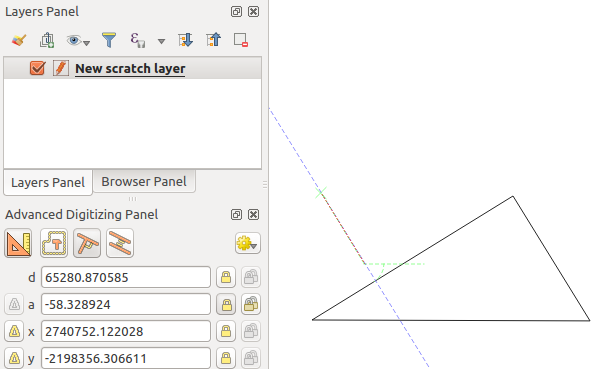
Perpendicular digitizing
To draw a parallel feature, the steps are the same: click on the Parallel icon (keyboard shortcut p twice), click on the segment you want to apply equally reference and get-go drawing your characteristic:
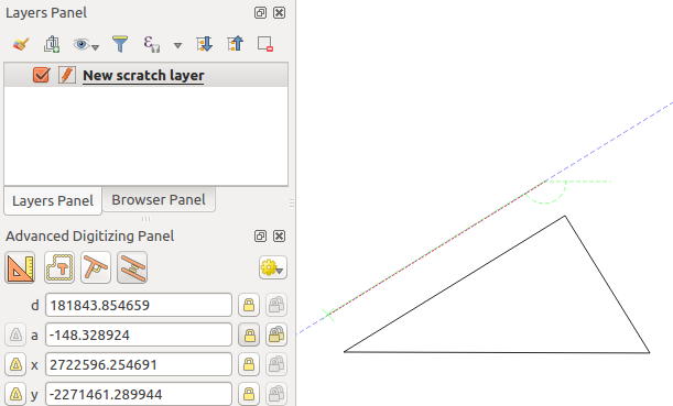
Parallel digitizing
These ii tools just find the correct bending of the perpendicular and parallel angle and lock this parameter during your editing.
Construction mode
You can enable and disable construction mode past clicking on the  Construction icon or with the c keyboard shortcut. While in construction mode, clicking the map sail won't add new vertexes, just will capture the clicks' positions then that you can use them as reference points to then lock distance, angle or x and y relative values.
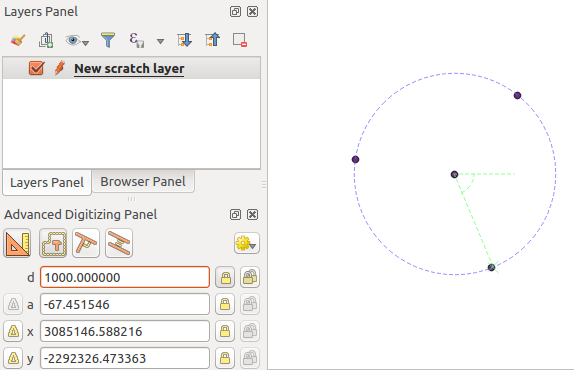
As an example, the construction mode can be used to describe some point at an exact altitude from an existing point.
With an existing point in the map canvas and the snapping way correctly activated, you can easily draw other points at given distances and angles from it. In improver to the button, y'all have to activate also the construction mode by clicking the Structure icon or with the c keyboard shortcut.
Click next to the point from which you want to summate the distance and click on the d box ( d shortcut) type the desired altitude and press Enter to lock the mouse position in the map canvass:
Altitude from point
Earlier adding the new signal, press c to exit the construction mode. Now, yous tin can click on the map sail, and the signal will be placed at the distance entered.
You can too use the angle constraint to, for case, create some other betoken at the aforementioned distance of the original i, but at a detail angle from the newly added indicate. Click the Construction icon or with the c keyboard shortcut to enter structure manner. Click the recently added signal, and then the other one to set a management segment. Then, click on the d text box ( d shortcut) type the desired altitude and press Enter . Click the a text box ( a shortcut) type the bending yous want and press Enter . The mouse position will be locked both in distance and bending.
Altitude and bending from points
Earlier adding the new signal, printing c to exit the structure mode. Now, you tin click on the map canvas, and the point will be placed at the distance and angle entered. Repeating the process, several points can be added.
Points at given altitude and bending

Source: https://docs.qgis.org/2.18/en/docs/user_manual/working_with_vector/editing_geometry_attributes.html
Posted by: yoderfiew1977.blogspot.com
0 Response to "How To Draw A Line Between 2 Vertices Pthon"
Post a Comment